How the work on the Point cloud in Revit is going on
Kseniya Kutsenko
08. 15. 2023
OPTIONS FOR WORKING IN REVIT
Point cloud projects are mostly done by a team of specialists, so there are several options for work:
Revit server. You need to create worksets for users and make sure that everyone works in their own set. To prevent the displacement of the cloud points from the initial coordinates, it is necessary to delete the cloud each time before synchronization with the central model, and then reload it again.
BIM 360 account. Each user has his own profile, so there is no need to create worksets. There is also no need to unload the cloud before synchronization.
BEGINNING OF WORK
Work on the point cloud in Revit takes place in certain templates. In most cases, the customer provides a template already configured for a specific 9oint cloud. In such a template, the MEP systems are already configured, and all the necessary sizes of architectural and structural elements.
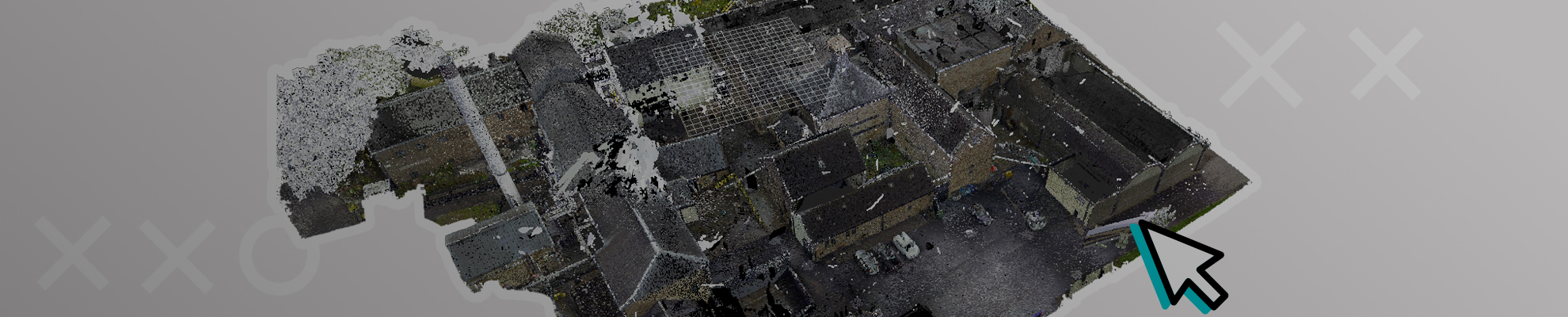
In all cases, except as agreed with the customer, it is recommended to load the cloud into the project at common coordinates (Auto > By Shared Coordinates). Next, you need to divide the model into levels, if they were not in the the project.
Before you start working in the Revit model, you need to perform the following actions:
- Go to the "Manage Links" window and check the location of the point cloud on your computer;
- Check your workset or profile, if using Bima 60;
- Make sure that the cloud is pinned (Pin) and has the "Existing" stage;
- Disable movement of pinned and linked objects;
- Create new views and sections for work by copying existing ones but adding your initials.
A FEW TIPS TO SIMPLIFY YOUR WORK
- It is better to work with two monitors so that 2 previously created sections can be displayed on a second monitor. This makes it possible to better control the position of the elements.
- On the quick access tab, you need to add buttons responsible for turning on and off the point cloud on a particular view and also a button to switch the cloud to the Normal visibility mode for a particular view.
- Hot keys, which can be added to your needs, and your modeling style.
SEQUENCE OF MODELING IN REVIT
- First of all, modeling of elements that are attached to the roof or floor (walls, columns). In turn, walls should not intersect with each other and other elements, for this there is a tool "Join/Unjoin";
- Columns often serve as loadbearing structures, so they are created using the "Structural column" tool;
- The floor is made with the "Floors" tool, sketching along the outer borders of the walls. After that, using the "Attach Top/Base" tool, align the walls, and columns with the floor, so that when changing the floor, the walls/columns move with it;
- We make the slab along the inner boundaries of the walls. It is necessary to take into account all existing slopes. Interfloor floors must be leveled on the inner surface relative to the cloud points, and mezzanine floors on the lower surface.
- Stained glass is modeled taking into account the panels on the point cloud, you also need to use the profile of the required section;
- Door s/Windows must be made as accurately as possible in width and height of the opening;
- When modeling beams, you must start with the main beams, and then move on to the beam's flooring. You also need to pay attention to the material of the beams, because it depends on docking with columns;
- Stairs are modeled with a special tool, the number of steps must coincide with their number in the cloud;
- The railing also has its own tool. The top of the handrail must coincide with the cloud, also Depending on the LOD, it is necessary to observe the coincidence of vertical elements on the Point cloud;
- All elements that can be attached to a separate level should be attached (columns, walls, etc.);
- It is better to make the ceiling separately for each room if another option is not agreed upon with the customer;
- The roof is made in one piece, after which the walls/columns are attached to it using the "Attach Top/Base" tool. After that, the roof is aligned with the point cloud;
- When all this is done, you can model the internal elements of the model.
DETAILING WHEN MODELING IN REVIT
When ordering a project, the customer always specifies the level of development of the information model LOD. LOD (Level of Detail) in BIM is a standard that defines the requirements for 3D geometry. Sometimes customers have their own internal standard of detailing that they must provide.
4 levels of LOD:
LOD 100 - model in the form of volumetric forming elements with approximate dimensions and shape.
LOD 200 - the model is presented as an object, more like a building, with approximate size and shape. It already displays window and door openings, railings by height on a point cloud.
LOD 300 - model with exact dimensions and shape. Door s/Windows with frames, panels, and railings completely behind the point cloud. The model can be used to prepare project documentation.
LOD 400 - the model is presented with detailed dimensions and shape. All elements must be made according to the point cloud.
FINAL STAGE OF MODELING
Once the project is done, it needs to be checked thoroughly. Programs for checking: Revit, Navisworks Manage.
The quality of the check depends on the final look of the project, the number of edits from the customer, and the rating of your service.
Checking in Revit is performed using the same sections and views as in modeling. But the check is aimed at finding missing elements, and inconsistencies with the point cloud. Each level is checked in section, all plans and ceiling plans are also checked (small elements such as sensors are especially noticeable on them). Worksets are also checked, it is better to check them in 3D view through the worksets color display menu.
Share:


SOCIAL MEDIA


© Copyright BIMPROVE company LLC. All rights reserved 2026. Privacy Policy.